MAP sensor intallation
The MAP sensor addition adds enhanced overboost protection and performance to your 944/951. With MAP, the DME is now able to read actual boost pressure and use it to adjust fuel and timing maps accordingly! Installing the MAP sensor is straight-forward, however attention to detail is important, as improper installation could result in DME or engine damage. For best results, the MAP sensor needs to be installed with minimal length vacuum line. The MAP sensor addition is a two-part installation; the first part is wiring the three wires of the sensor:

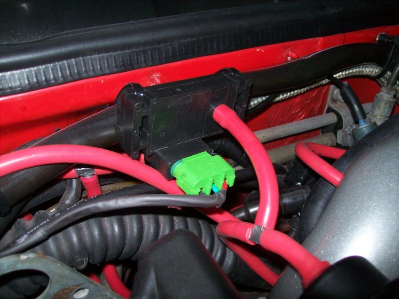
The MAP sensor:

The MAP sensor has a vacuum/boost port on its underside. This port needs to be connected to the port on the intake manifold. Typically, T-ing off of the vacuum line going to the fuel pressure regulator provides good results. Additionally, the length of tubing from the MAP sensor to the intake manifold should be kept less than three feet long. This helps keep the MAP sensor response time very fast.
The MAP sensor comes with a three-wire harness, that is color-coded:
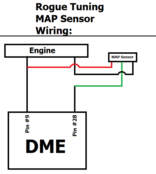
MAP sensor: DME:
- (5v) Red # 9 Green/Yellow*
- (gnd) Black # 28 Black* (Engine side)
- (sig) Green # 28 Black* (DME side)
The MAP sensor harness is long enough to place the sensor in the engine-bay and run the wires through the firewall boot/seal to the DME.
The Red power wire is tapped, that is - do not cut the DME's respective wire, just remove some of the DME wires insulation and connect the MAP sensor wire. As always, we recommend soldering, not T-type or "vampire" clips. A poor connection here can significantly reduce the MAP sensor signal.
For the Green signal wire, the DME wire 28 needs to be cut, and then connect the MAP sensor Green wire to the wire going to the DME. Then connect the MAP sensor Black wire to the cut wire that goes towards the engine.
***The DME wiring colors could be different depending on the build date of your car***
Here is a quick visual to follow:
Now that the MAP sensor is wired in, a simple voltage check will confirm that it is working properly:
With the ignition on, measure the voltage on the red wire to ground. You should see +5volts.
Now measure the voltage on the green wire. This should read ~1.6 volts (this will vary slightly depending on altitude).
If either wire does not read correctly, double-check your connections and that they are going to the proper wires in the DME harness.
Modify the DME:
The second step necessary to install the MAP Sensor is removing/cutting a resistor in the DME itself. This is necessary for the DME to properly read the MAP sensor. The resistor on the same side of the DME that the EPROM is. If you are comfortable with soldering you can de-solder the resistor and remove it. Alternatively, you can simply cut one of the resistors legs, and bend the resistor out of the way - making sure it does not come into contact with the DME board:


Depending on the year of your DME, the body of the resistor might be a different color.
***Cutting/removing this resistor does not affect normal function of the DME, regardless of software***
The DME Plug:
In order to properly identify DME's pin # 28, it is necessary to disassemble the DME plug. Once the cover is off, the pin numbering becomes visible:


Pin # 28 tends to be black on the 951. Double-check that you cut the correct wire by using a volt-ohm meter to verify continuity between pin # 28 and the wire you plan on cutting!
MAP Sensor Mounting: